


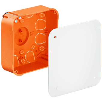
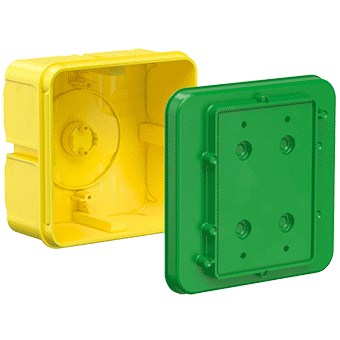


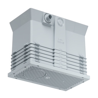


Central transition casing
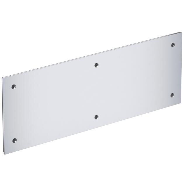
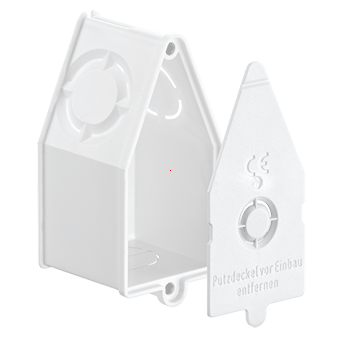
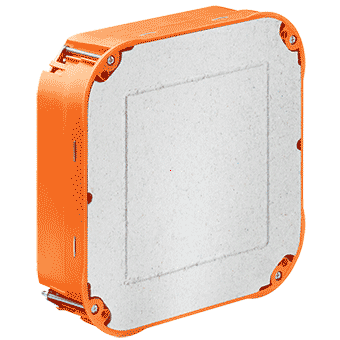
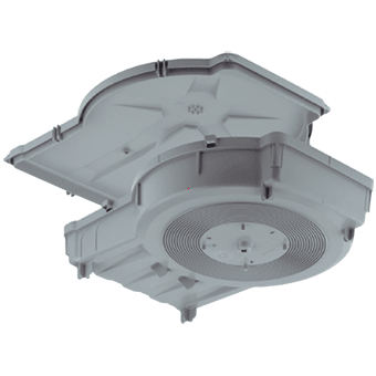
Screw-on cover (330 x 120 x 5 mm) for Art. No. 9914.10
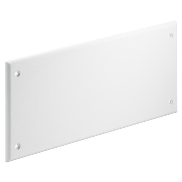

Screw-on cover (330 x 120 x 5 mm) for Art. No. 9914.10


- Article no: 9914.10.02
- EAN: 7611614453828
Length
330 mm
Width
120 mm
Height
5 mm
Colour
RAL 9010
Screws
6
For type number
9914.10
Dispatch
150
Product information
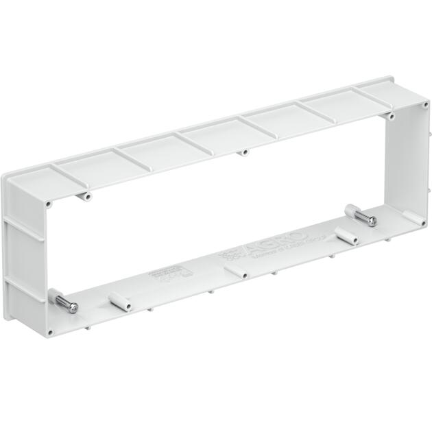
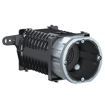
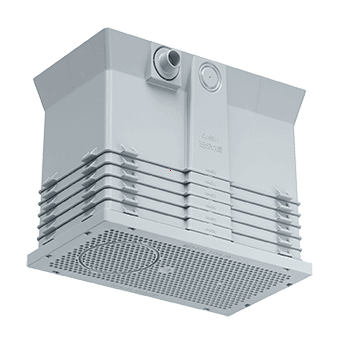
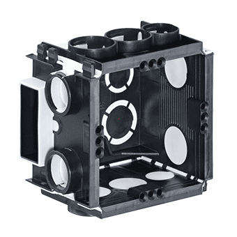
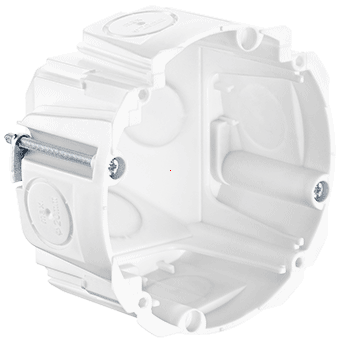
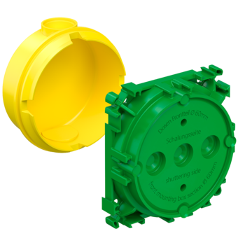
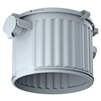
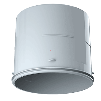
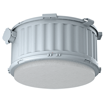
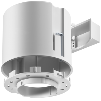
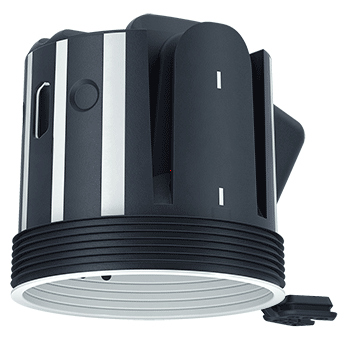
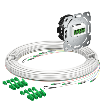
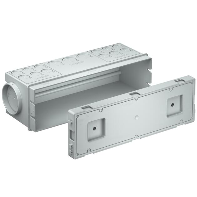
Central transition casing
The new central transition box for use in on-site mixed concrete ceilings or factory prefabricated element ceilings is used for the central connection of conduits of different diameters. As a central feed-in point, it enables a clean transition to circuit distribution boxes and cable routing systems, allowing, for example, all the supply cables required for the electrical installation of a flat to be brought together at one transition point.
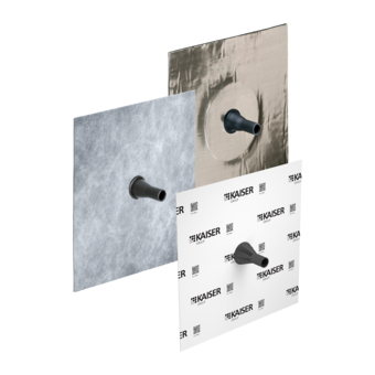
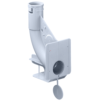
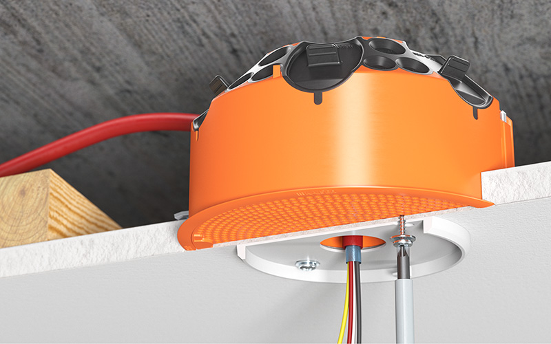
- For leaving out several cables, e.g. above an electrical distribution board located in the lightweight wall or surface-mounted
- For system magnetic, adhesive or nail fastening
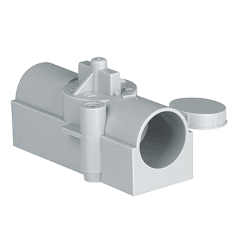
- Conduit entries for Ø 20 mm, Ø 25 mm and Ø 32 mm on the long sides, up to Ø 63 mm on the short sides
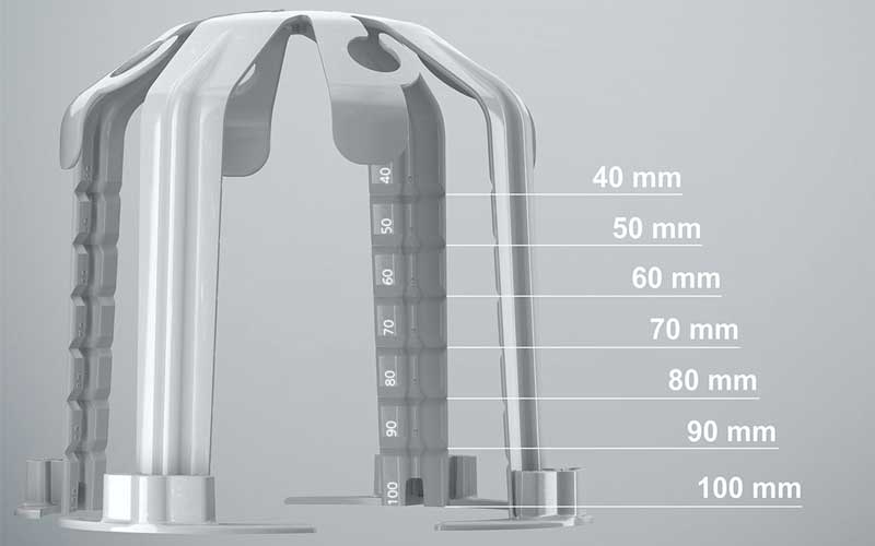
- Positioning of the conduit entries above the first reinforcement layer or the top of the filigree ceiling
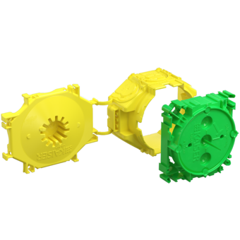
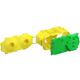
- Can be connected in a row as often as required


Application examples


Processing instructions


Installation


Download


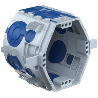
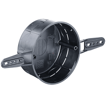
Product recommendations
Planning

Similar products